Completion Optimization

This is one of our core activities and strengths. We regard ourselves to be one of the industry leaders in the field of optimization of completion designs. Engenya worked with Halliburton for over a decade to develop and validate their advanced perforation shock simulation tool, ShockSim3D®. Now Engenya is able, together with its partners, to offer independent completion simulation and optimization services using ShockSim3D® under license form Halliburton, as well as a suite of proprietary extensions that render the handling of data and interpretation of results for the purpose of minimizing risk while maximizing productivity, more efficient and intuitive.

Although simulations of the completion process have been conducted by the energy services companies for a long time, this has usually been linked to their services. An independent capability to run these simulations at an unprecedented level of resolution now provides operators the ability to make their own decisions and optimize their own designs. Such a powerful tool can be employed both in a predictive sense to manage risk and optimize performance, as well as in an analytical sense to validate jobs or understand the causes of unexpected failures.

Read on, and learn how we can help you optimize the productivity of your completions…

Background

The development of ShockSim3D® began after Halliburton experienced a gun parting failure in the field that was hard to explain, and that had not been predicted by the legacy simulation software. It was in the process of applying state of the art modelling and simulation methods to determining the underlying causes of this failure that the potential for use in a routine high fidelity tool was realized. Another key realization was that this new tool would need to be validated with field data but that a suitable sensing tool that could be placed directly in the perforation interval, did not exist. With this, the development of ShockSim3D® (SS3D) and the Shock Sensing Sub (SSS, now marketed as the HPET tool) was kicked off.

Initially, the goal was to address and manage the risk of failure of the structural components of typical perforation jobs in offshore wells. To do this reliably, however, the simulation had to be sufficiently accurate and validated. It became clear that the resolution with which the pressure dynamics could be calculated provided far more insight into the dynamics that are generated by the release of explosive energy during perforation than the legacy tools could do.

Engenya is now able to offer an independent completion design and optimization service using the SS3D suite as one of the principal tools at its disposal.

Development

main_failure
Gun Parting Failure
Testing
Charge Model Calibration
tool-401x1024
Downhole Tool Design
calibration
Completion Dynamics

SS3D and SSS development was started concurrently. SS3D was built to resolve the complex fluid and structural dynamic response generated by the explosive energy release during the well perforation process for the purpose of minimizing the risk of structural failure while optimizing job performance. It is built around the LS-Dyna commercial solver. LS-Dyna’s capabilities enable the handling of both the CFD and FEA parts of the coupled solution in a single, proven solver.

At the same time as the solution methodology was being developed, a proprietary pre-processor and model builder was being coded. A dedicated model generator would provide significant advantages in being focused on generating SS3D models by rendering the process much more efficient. With the introduction of Model Builder, model generation times dropped by 80 – a model could now be built in a matter of a day or two rather than two weeks.

In the meantime, SSS was being completed and tested. With SSS we began to run charge calibration tests. These were critical for ensuring that our representative explosive charge models released the appropriate amount of energy once detonated. The match between simulation and test of different types of charges was excellent. This enabled us to continue to calibrate the full model against real world data. For information on these activities, please view the projects highlighted in the thumbnails.

Since its launch, SS3D has proven its worth on numerous wells. Its original capabilities have been continuisly extended to deal with new types of tools and well situations. A formation and cleanout model was added to enable the simulation to be extended beyond the first few hundred milliseconds that are relevant for structural integrity. This allows SS3D to estimate skin values and potential productivity.

Engenya has since extended the data handling and post processing capabilities further to make the optimization of the completion design more intuitive by developing proprietary data handling routines.

The solution remains flexible and customizable for your specific needs.

Capabilities

ShockSim3D® offers a range of features that enable solution capabilities far surpassing those available in legacy software:

  • 2-D Axisymmetric fluid model coupled to a full 3-D solid model of the completion string.
  • High resolution of fluid (sub inch) and solid model (inch) meshes, optimized over the length of the string.
  • Individual charge model representation for accurate energy and pressure distribution within the guns.
  • Model resolution tuned to enable shock to be captured.
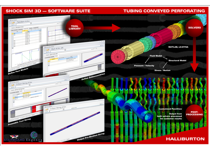
  • Complete flexibility in the definition of tools and components through a tool library.
  • Full results database that allows extraction of results from any location in the model.
  • Equation based cleanout model for estimation of local skin values.
  • Equation based formation model for local fracture propagation estimates.
  • Ability to handle multiple perforation zones.
  • Ability to handle multiple detonation zones.
  • Ability to simulate the use of propellants.
  • Fracture propagation model.

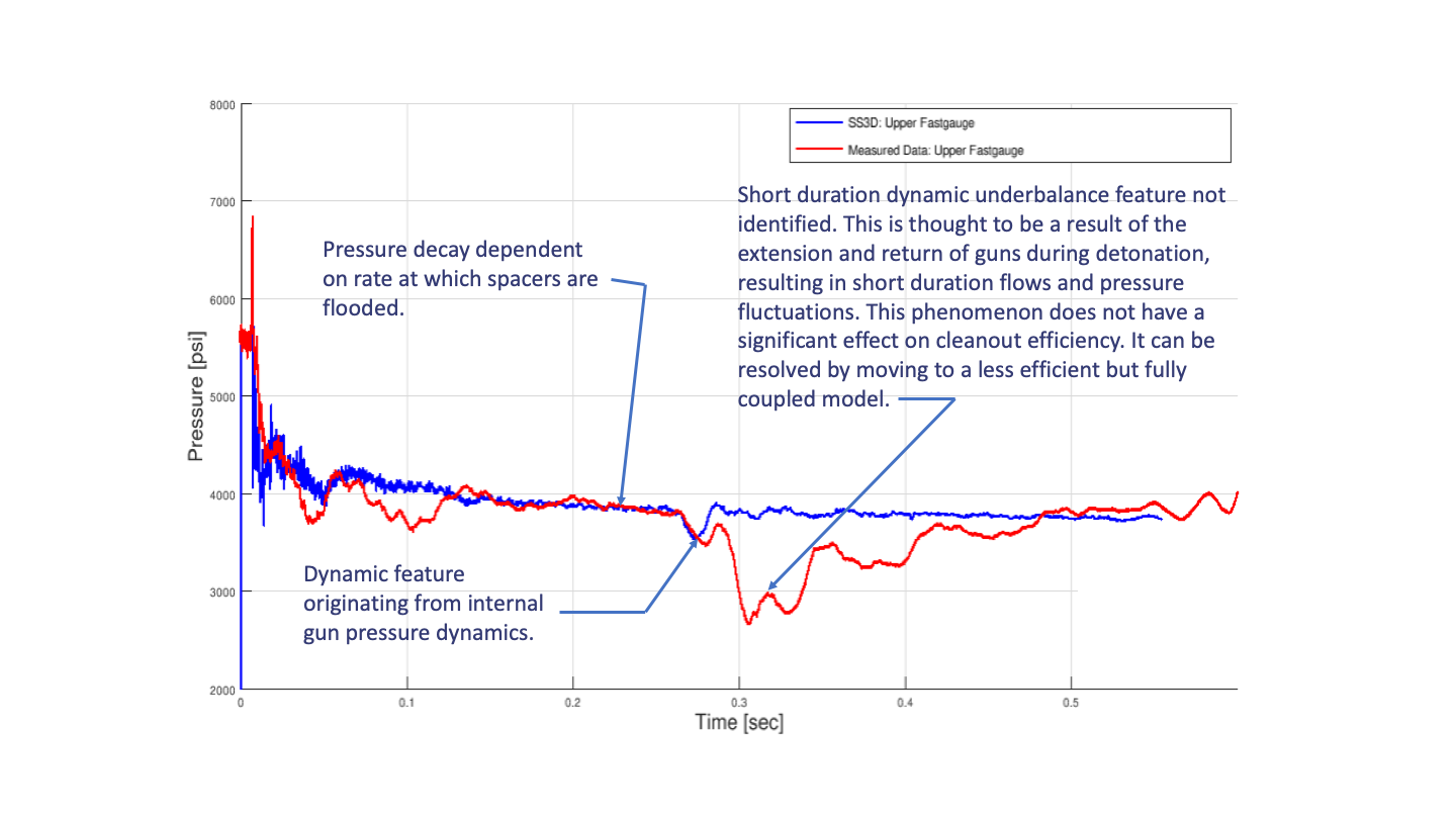
These features make it possible for SS3D to resolve the dynamic pressure response throughout the gun string, the entire wellbore, annulus and perforation tunnels, as well as resolving the structural dynamic response of the gunstring itself at an unprecedented level or accuracy and detail. SS3D solution capabilities include:

  • High resolution pressure dynamics, fluid velocity and material transport results.
  • Accurate calculation of local dynamic underbalance (DUB).
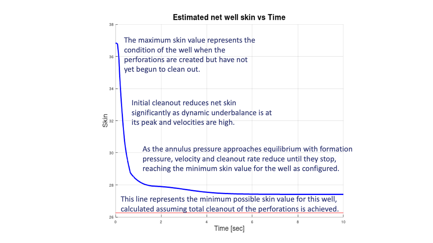
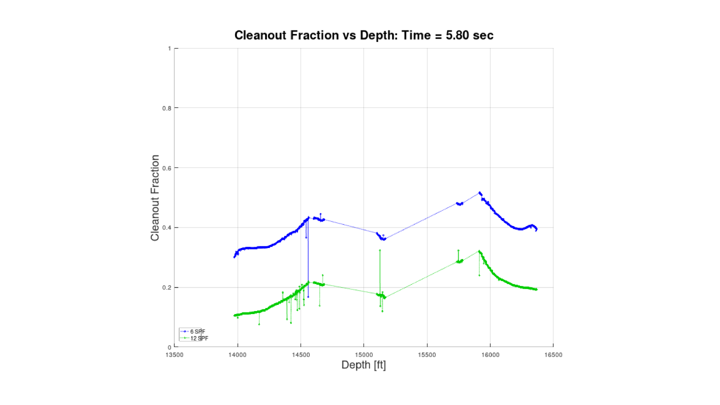
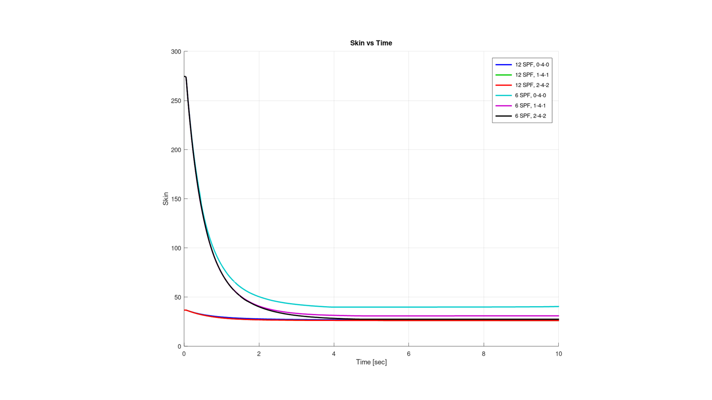
  • Estimation of local perforation tunnel cleanout and resulting skin.
  • Estimation of total well skin.
  • Formation fracture estimation.
  • Structural loads, stresses and deformation of gun string components due to gravity, contact, friction, dynamic loads, etc.
  • Identification of gun string component failure modes such as buckling, burst/collapse, packer damage, sensitive tool overload, gun dynamic fracture, excessive acceleration levels on measuring equipment, non-linear impact effects, charge tube stackdown, etc.

These capabilities can be harnessed for a range of services:

  • Predictive analysis of perforating jobs to quantify risk of structural failure and expected loads.
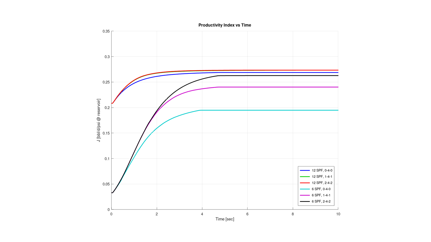
  • Predictive analysis of perforating jobs to estimate expected well skin and productivity index.
  • Sensitivity analyses to evaluate system performance for different design configurations.
  • Post job validation with downhole data.
  • Post job analysis in case of discrepancies with expected performance or failure.
  • Assessment of gun system design in a relevant environment.
  • Customized calibration of new gun systems and charges.
  • Customized high fidelity models of specialized tools.

We believe, however, that the maximum value lies in integrating this simulation capability into the completion design process from the beginning. Ideally, Engenya’s contribution would be split into three phases:

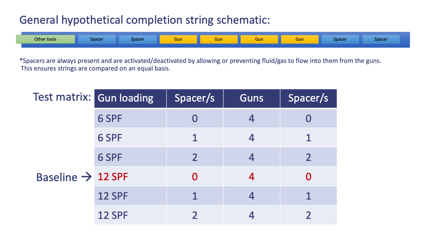
  1. Concept design phase – when you start designing your completion we would run through multiple sensitivity analyses to assess the optimal distribution of charges and free volume in order to leverage the pressure dynamics to maximize perforation tunnel cleanout (something which to this day no one really does). Such a sensitivity study would consider variables such as gun system type, charge type, shot density vs depth, spacer distribution, internal spacer flow rate, external spacer flow rate, initial pressure, etc. The result of this study would drive the final completion design.
  2. Detailed design phase – the knowledge gained in the concept phase is put into practice and a final design for the completion, based now on accurate well and formation data, is generated. If there is still uncertainty in the selection of components and specific variables, a limited sensitivity analysis can be done.
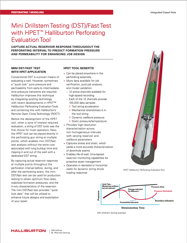
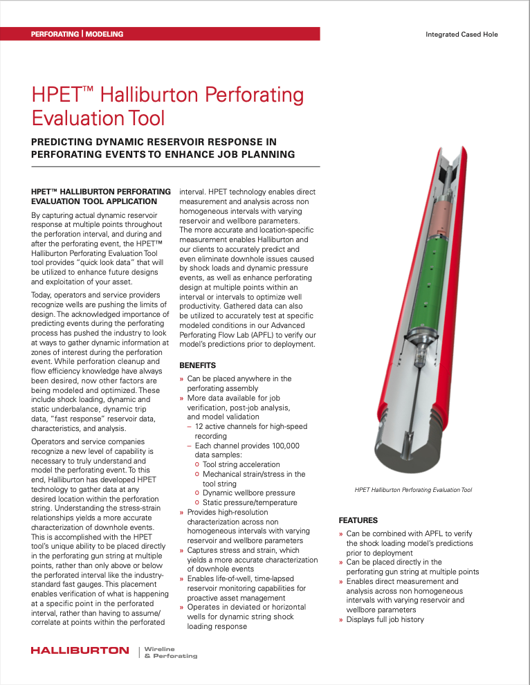
  3. Post job – once the job is run, data is collected for later validation of the model predictions. Data can be collected with any standard pressure gauge tool or Halliburton’s HPET tool that also provides structural loading data. This step is valuable to verify and improve models, particularly in multi-well campaigns.

Regardless of your need, we can offer a service that fits and, perhaps more importantly, that is independent.

Examples

After completing a well, an operator found that the flow resistance was significantly higher than that predicted by legacy software, indicating a substantially higher overall skin value. Engenya was asked to run a post job calibration analysis and determine the cause of this discrepancy. The calibrated model confirmed that the expected skin value had been too low and calculated a value much closer to that encountered in practice. The cause of the difference was the optimistic prediction of the duration of dynamic underbalance by the legacy software that calculated more effective cleanout than was possible in reality with the completion as designed. The top image on the left compares the calibrated model pressure to the measured pressure at the gauge location, just above the completion interval. Because the model’s resolution enables the calculation of cleanout and skin values down to single perforation resolution, integrating this over the length of the completion results in a total well skin value that can be used to calibrate against flow tests. The second image shows the progression of the total skin value over time as the dynamic underbalance drives perforation cleanout. The measure of cleanout efficiency comes from the comparison with maximum cleanout possible, leaving only geometric factors to determine skin values.

As you can see in the two animated graphs (centre), results can be presented as a function of depth and time, which gives you a clear picture of the evolution of the well during the perforation process. Any result can be viewed this way: DUB, cleanout, skin, productivity index, etc., maximizing the insight you can gain from the large quantities of data that the solution generates.

The calibrated model was subsequently used to demonstrate how SS3D can be used to evaluate and optimize different completion string designs. In this simple example, the differences in dynamic underbalance and resulting cleanout for two different shot densities are shown in the last two images. It is clear that a lower shot density results in more effective cleanout because the larger free volume extends the pressure draw down and resulting dynamic underbalance. In practice, this improvement in cleanout efficiency must be balanced with the geometric skin factors to determine the optimal solution for maximum communication. This would represent a more rigorous systems oriented approach to completion design that would balance the management of risk to structural integrity while maximizing productivity.


The second example is the hypothetical optimization of a short, 4-gun string, focusing only on free volume and shot density as variables. In this case, the string is set up as shown in the first image. Two spacers flank either side of a string of 4 fully loaded guns. The fluid communication to the spacers can be allowed or denied. This allows us to compare similar strings with different levels of free volume directly.  The baseline case is the 4-gun string with 12 SPF charge loading and no active spacers. Charge loading can be either 6 SPF or 12 SPF.

The second image shows the final cleanout fraction achieved for each configuration. The simulation ran long enough to ensure the well bore and formation pressures had equilibrated and no DUB was evident. Only two configurations achieved total cleanout: 6 SPF with 4 active spacers and 12 SPF with 4 active spacers. At this point, the well skin is only determined by the geometric factors of the completion design. Ultimately, we see that well skin is very similar for the configurations with 12 SPF and the PI is generally equivalent. However, it is also evident that the 6 SPF configuration has the potential to get close to the PI of the 12 SPF configuration given sufficient free volume to generate and extend DUB. The importance of this determination is seen on the last slide.

This case is, of course, highly simplified and certainly not representative of the complexities that a real long string would generate in its optimization. These complexities would, however, present opportunities and levers for optimization that this simple case cannot do. Look at the last slide – by adding a spacer to the baseline case, either side of the guns, it is possible to maximize the productivity. Additional spacers make no difference. Note the 6 SPF case with 4 spacers though. The conclusion is the with half the charges and additional spacers, we can achieve almost the same productivity. The cost of the equipment, though, is significantly lower.

This is by no means an exhaustive optimization, but it does show the potential that exists in spending a bit more time up front really thinking about the completion design. In this example we picked some variables at random – perhaps with 8 SPF and a couple of spacers we may have been able to math the productivity of the best 12 SPF string. Now, scale this up to your wells and completions…

Applications

We have run simulations, either directly or for Halliburton, on the following wells:

Operator
Well/Field
Beacon Offshore Energy
Shenandoah
BHP
Shenzi
BP
ACG
BP
Thunderhorse
Chevron Corporation
Agbami
Chevron Corporation
Tahiti
Chrysaor
Dunnottar
ConocoPhilips
West Limb
ECO Oil & Gas
CAN
Hess Corporation
Baldpate
Hess Corporation
Stampede
Husky Energy
SWRX
Marathon Oil
Droshky
Medco
Buntal
Medco
Hiu
Murphy Oil Corporation
Frontrunner
Murphy Oil Corporation
Thunderhawk
Noble Energy
GC
Noble Energy
MC
Occidental Petroleum
OEH
Petrobras
BUZ
Petrobras
Chinook
Petronas
KN
Premier Oil
Solan P2
Premier Oil
Solan P3
Shell
E6
Shell
Europa
Shell
Glider
Shell
Heron
Shell
Olympus
Shell
PowerNap
Shell
Whale
Statoil
Gulfaks
Talos Energy
A
Total
Culzean
Tullow Oil
EN09-WI
Tullow Oil
NT05-P
Woodside Petroleum
KDA

References

Engenya GmbH partners with the following companies to provide a full completion design and optimization service:

Halliburton products involving either ShockSim3D® or the HPET (Shock Sensing Sub), or both:

Papers and presentations: